Decoding the Elegance of Relay Coil Symbols
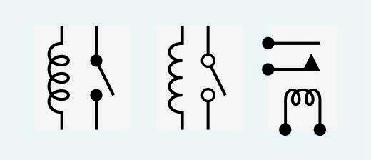
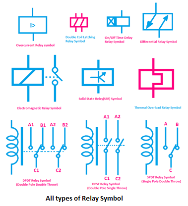
Within the intricate tapestry of electrical schematics, there's a subtle elegance to the symbols employed – each a shorthand narrative of a component's function. Among these, the relay coil symbol holds a particular significance, representing a crucial element in controlling electrical circuits. This exploration delves into the visual language of relay coil symbols, unraveling their historical context, practical applications, and the subtle nuances that differentiate their various forms.
Imagine the relay as a silent conductor, orchestrating the flow of electricity within a circuit. The relay coil, the heart of this conductor, acts as an electromagnetic switch. When energized, the coil generates a magnetic field that activates the relay's contacts, opening or closing circuits as designed. This seemingly simple action underpins a wide range of applications, from controlling high-power devices with low-voltage signals to implementing complex automation sequences.
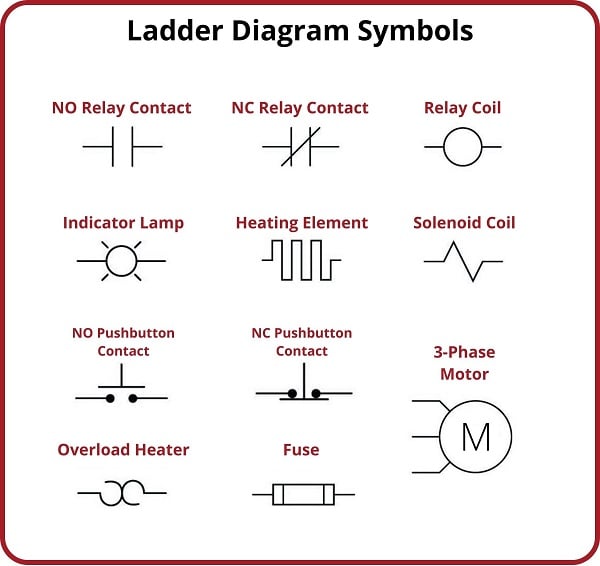
The graphical representation of a relay coil, its symbol, is more than just a convenient shorthand. It’s a universal language, allowing engineers and technicians across the globe to understand the function of a component at a glance. These symbols have evolved over time, influenced by both technological advancements and standardization efforts. Understanding this evolution provides a deeper appreciation for the symbolism we use today.
The importance of accurately interpreting and utilizing relay coil symbols cannot be overstated. A misinterpretation on a schematic can lead to faulty circuit design, potentially resulting in malfunctioning equipment or even safety hazards. Therefore, a clear understanding of these symbols is paramount for anyone working with electrical systems.
Different types of relays, each with its unique characteristics, are represented by variations in the coil symbol. For instance, a latching relay, which maintains its state even after the energizing signal is removed, has a distinct symbol that distinguishes it from a non-latching relay. Similarly, polarized relays, sensitive to the direction of current flow, are represented by symbols that reflect this characteristic. Recognizing these subtle variations is essential for accurate circuit interpretation.
The relay's history intertwines with the development of telegraphy in the 19th century. Joseph Henry, an American scientist, is often credited with inventing the relay's precursor, the electromagnetic sounder, in the 1830s. Subsequent innovations led to the development of the electromechanical relay, paving the way for complex switching and control systems. This evolution also shaped the standardization of relay coil symbols.
One benefit of using standardized relay coil symbols is improved communication among engineers. A universal language minimizes ambiguity and facilitates collaboration on complex projects. Another benefit is enhanced circuit analysis and troubleshooting. Clear and consistent symbols simplify the process of understanding circuit operation, allowing for quicker identification of potential issues. Finally, standardized symbols contribute to efficient documentation, ensuring that electrical schematics are readily understandable by anyone familiar with the conventions.
An action plan for effectively utilizing relay coil symbols starts with learning the basic symbols and their variations. This includes understanding the representations of different relay types, such as latching, non-latching, and polarized relays. Next, practice reading and interpreting electrical diagrams containing relay coils. Finally, consult relevant standards and resources to stay updated on any changes or additions to the symbolic language.
Advantages and Disadvantages of Standardized Relay Coil Symbols
| Advantages | Disadvantages |
|---|---|
| Clear communication | Requires learning and understanding |
| Efficient circuit analysis | Potential for misinterpretation if not used correctly |
| Simplified documentation | Can be complex for highly specialized relay types |
Five best practices for implementing relay coil symbols: 1. Adhere to established standards like IEC or IEEE. 2. Clearly label all relay coils with designations. 3. Ensure consistency in symbol usage throughout the schematic. 4. Provide a legend or key explaining any non-standard symbols. 5. Use software tools with built-in symbol libraries for accurate representation.
Challenges related to relay coil symbols can include variations in representation across different standards, understanding complex symbols for specialized relay types, and keeping up with updates to symbolic conventions. Solutions involve referencing authoritative sources, seeking expert guidance, and utilizing software tools that maintain updated symbol libraries.
Frequently Asked Questions: 1. What is the basic symbol for a relay coil? 2. How is a latching relay coil represented? 3. What is the difference between a normally open and normally closed relay contact symbol? 4. Where can I find a comprehensive list of relay coil symbols? 5. How do I represent a polarized relay coil? 6. What are some common applications of relays in electrical circuits? 7. What are the key considerations when selecting a relay for a specific application? 8. How can I troubleshoot a circuit containing a faulty relay?
(Provide general answers for each question.)In conclusion, the seemingly simple relay coil symbol represents a powerful concept in electrical engineering. Understanding its nuances is crucial for effective circuit design, analysis, and troubleshooting. From its historical origins in telegraphy to its diverse applications in modern technology, the relay coil remains a fundamental component. The accurate interpretation and utilization of its symbolic representation ensures clear communication, efficient circuit operation, and ultimately, the successful implementation of electrical systems. Embrace the elegance of these symbols, for they unlock the language of electrical control.
Navigating the unam law degree curriculum
The illuminating power of laser lighted signs a comprehensive guide
Phoenix tattoos women black and white a timeless symbol of rebirth


