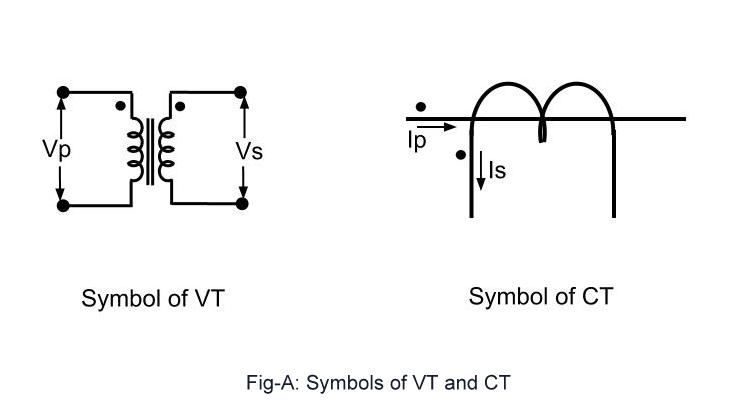
Decoding the Potential Transformer One Line Symbol
Ever glanced at an electrical diagram and felt a surge of bewilderment? Like staring at a cryptic message from a forgotten civilization? Those squiggles, dashes, and circles aren't random doodles; they're a language, and understanding them is crucial, especially when it comes to the potential transformer one line symbol. This seemingly simple representation packs a punch, conveying a wealth of information about a critical component in power systems.
The potential transformer one line symbol is more than just a convenient shorthand; it's a cornerstone of electrical diagrams. It represents a device that steps down high voltage to a safer, measurable level. Imagine trying to monitor the massive voltage coursing through a power grid directly—talk about a shocking experience! Potential transformers (PTs), also known as voltage transformers, allow us to do this indirectly, protecting both equipment and personnel.
So, why is the one-line symbol so important? In complex electrical systems, clarity is king. One-line diagrams, utilizing these symbols, provide a simplified representation of the system's components and connections. They strip away unnecessary details, offering a clear overview without getting bogged down in the minutiae of every wire and connection. The potential transformer one line symbol, within this context, pinpoints the PT's location and function, contributing to a readily understandable schematic.
Historically, the need for potential transformers arose with the expansion of AC power systems. Managing and monitoring these higher voltages demanded a safer approach. The potential transformer emerged as the solution, allowing accurate voltage measurements without direct exposure to dangerous high-voltage lines. The evolution of its symbolic representation mirrored the growing complexity of electrical systems, culminating in the concise and informative one-line symbol we use today. Its standardization across the industry ensures consistent interpretation and facilitates clear communication among engineers and technicians worldwide.
The potential transformer one line symbol typically resembles a coil or winding with a connection to the primary (high-voltage) side and another to the secondary (low-voltage) side. Variations might include additional markings to indicate grounding or specific configurations. Understanding these subtle differences within the symbol can provide valuable insights into the PT's specific role in the circuit.
A basic potential transformer one-line symbol might look something like this (using text representation): ---(PT)--- . This simple depiction conveys the presence of a PT within the circuit. More detailed versions can include information about the voltage ratios, connection type, and other relevant parameters.
Benefits of using a PT symbol include simplified circuit diagrams, easier analysis of power systems, and efficient communication among electrical professionals. Examples include quickly identifying PT locations in substations, understanding voltage transformation within a circuit, and designing protection schemes based on accurate voltage readings.
Best practice is to adhere to standardized symbols. Consult IEEE or IEC standards for detailed representations. Always clearly label the PT symbol with its associated voltage ratio and other relevant information.
Advantages and Disadvantages of Potential Transformers
While advantageous, PTs also have limitations. For example, they can introduce errors in measurements due to their inherent impedance.
Frequently Asked Questions:
1. What is a PT? A: A device that steps down high voltage.
2. Why are PTs used? A: For safe voltage measurement and system protection.
3. What does the symbol look like? A: It resembles a coil or winding.
4. What are the benefits of using PTs? A: Safety, accurate measurements, and system protection.
5. What are the limitations of PTs? A: Potential measurement errors and cost considerations.
6. Where can I find more information on PT symbols? A: IEEE and IEC standards.
7. What are some real-world examples of PT usage? A: Substations, power plants, and industrial facilities.
8. What are some common challenges with PTs? A: Ensuring accuracy, dealing with ferroresonance, and proper grounding.
Tips and tricks: Always double-check the symbol's meaning in the context of the specific diagram. Refer to relevant standards for clarification.
In conclusion, the potential transformer one line symbol plays a pivotal role in simplifying complex electrical systems. Its concise representation provides crucial information about voltage transformation, enabling safer monitoring and control of power flow. From facilitating efficient communication among engineers to ensuring accurate voltage measurements, the potential transformer one line symbol is an indispensable element in the world of electrical engineering. Its standardized form ensures clarity and consistency across diverse applications, from large-scale power grids to intricate industrial installations. Mastering the meaning and application of this symbol is essential for anyone working with electrical diagrams, contributing to a deeper understanding of power systems and promoting safer practices within the industry. Understanding and utilizing this symbol empowers professionals to design, analyze, and maintain electrical systems with greater efficiency and safety, ultimately contributing to a more reliable and robust power infrastructure.
Conquering the california dmv permit test your ultimate guide
Wrangling your mustangs wheels the lug nut socket saga
Unlocking genesis insights exploring skip heitzigs teachings on youtube


