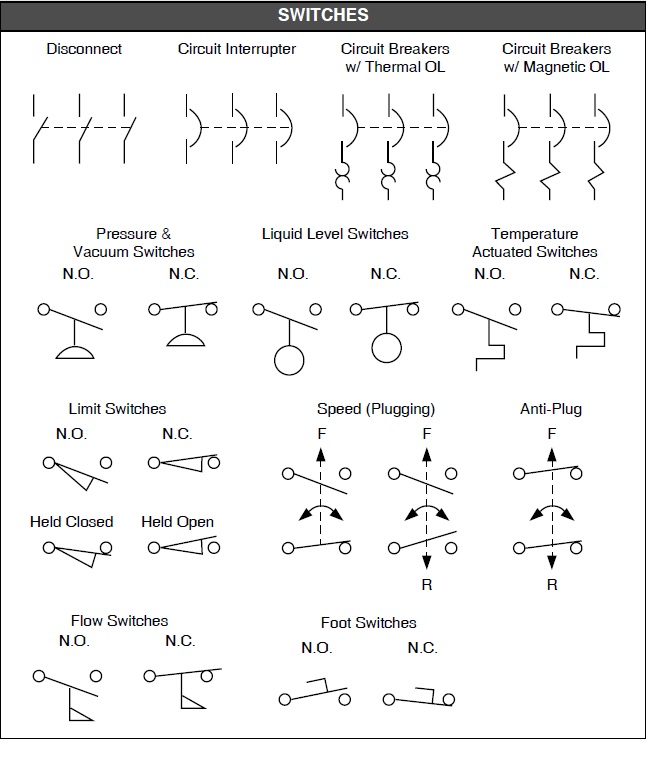
Decoding the Secrets of Schematic Switch Symbols
Ever stare at a circuit diagram and feel like you're deciphering ancient hieroglyphics? Those cryptic symbols, particularly the ones representing switches, hold the key to understanding how electricity flows and controls the magic of modern electronics. Seriously, without these little guys, your phone would be a brick, your car a hunk of metal, and your smart home, well, just dumb.
Schematic switch symbols, those little graphic representations of switches on circuit diagrams, aren't just arbitrary squiggles. They're a universal language, a shorthand for engineers and hobbyists to communicate the function and type of switch in a circuit. They’re essential for designing, building, and troubleshooting everything from simple light switches to complex computer systems. Imagine trying to explain a complicated circuit without them. It would be like trying to explain the plot of "Inception" without using words.
From the simplest on/off switch to complex multi-pole configurations, each switch symbol tells a story. It reveals how the switch controls the flow of current, allowing designers to visualize how the circuit will operate. Understanding these symbols is fundamental to anyone working with electronics, whether you're designing a new gadget or just trying to fix a broken appliance.
The history of these symbols is intertwined with the development of electrical engineering itself. As circuits became more complex, the need for a standardized way to represent components arose. Over time, these symbols evolved, becoming more refined and standardized to ensure clear communication across the industry. Early diagrams might have used more pictorial representations, while modern symbols are more abstract and focused on function. This evolution reflects the increasing complexity of circuits and the need for a more concise and universally understood symbolic language.
The importance of standardized switch symbols cannot be overstated. They facilitate collaboration, prevent misinterpretations, and ultimately ensure the safe and proper functioning of electrical systems. Without a common language, designing and troubleshooting circuits would be a chaotic mess, leading to errors and potential hazards. These symbols are the bedrock of circuit design, enabling engineers to create complex systems with precision and reliability.
A basic single-pole single-throw (SPST) switch, the simplest type, is represented by a line with a break and a small perpendicular line indicating the actuator. This symbol signifies a switch that either connects or disconnects two points in a circuit. More complex switches, like double-pole double-throw (DPDT) switches, have more intricate symbols reflecting their ability to control multiple circuits simultaneously. For example, a DPDT switch symbol shows two sets of contacts, each controlled by the same actuator, allowing for switching between two different circuits.
Benefits of using schematic switch symbols include: clarity in communication, simplified design process, and efficient troubleshooting. For example, a clear understanding of the symbol for a three-way switch allows an electrician to quickly wire it correctly without needing extensive verbal instructions.
When drawing circuit diagrams, accuracy in using switch symbols is paramount. Ensure the correct symbol is used for the specific switch type and that its orientation reflects the intended function. This precision is essential for preventing errors during circuit construction and operation.
Advantages and Disadvantages of Standardized Switch Symbols
| Advantages | Disadvantages |
|---|---|
| Universal understanding | Requires learning the symbols |
| Simplified circuit representation | Can be complex for highly specialized switches |
| Facilitates troubleshooting | Variations in style can sometimes cause confusion |
Best practices for using schematic switch symbols include: referencing standardized symbol libraries, maintaining consistent symbol usage throughout a project, and clearly labeling each switch in the diagram.
Real-world examples include the use of switch symbols in automotive wiring diagrams, building electrical plans, and electronic device schematics.
Challenges in using schematic switch symbols can include keeping up with evolving standards and dealing with variations in symbol libraries. Solutions include adhering to recognized standards like those from the IEEE and using software tools that offer consistent symbol libraries.
FAQs: What is a SPST switch? What is a DPDT switch? What does a momentary switch symbol look like? How are switch symbols used in PLC programming? What are the common standards for switch symbols? How can I learn more about switch symbols? What resources are available for understanding switch symbols? What is the difference between a normally open and normally closed switch symbol?
Tips and tricks for working with switch symbols include using online symbol libraries and practicing drawing common switch symbols to improve familiarity.
In conclusion, schematic switch symbols are the unsung heroes of circuit design. They provide a universal language that enables engineers and technicians to communicate effectively, ensuring the smooth operation of everything from simple household appliances to complex industrial systems. Understanding these symbols is not just about deciphering a diagram; it's about understanding the fundamental principles of how circuits work. By mastering these symbols, you unlock the power to design, build, and troubleshoot circuits with confidence and precision. This knowledge empowers you to engage with the world of electronics on a deeper level, opening up a world of possibilities for innovation and problem-solving. So, next time you see a circuit diagram, take a moment to appreciate the power contained within those seemingly simple switch symbols. They are the silent conductors of the electrical world, orchestrating the flow of electrons that powers our modern lives.
The resurgence of the female knight in digital comics
Keeping your boats heart beating a guide to boat motor water pumps
Building a stronger faith together essential questions for christian couples


