Understanding Marine Battery Isolator Switch Wiring
Ever wondered how your boat's electrical system keeps humming along, even when you're anchored for days? A key component is the marine battery isolator switch, a seemingly simple device with a crucial role. This article delves into the world of marine battery isolator switch wiring diagrams, unraveling their complexities and highlighting their importance for a reliable onboard power system.
Imagine being stranded at sea with a dead starting battery. A properly wired battery isolator prevents this nightmare by allowing you to charge multiple batteries from your engine's alternator while keeping them electrically isolated. This ensures you always have a dedicated battery for starting your engine, regardless of how much power you use for other onboard systems.
Understanding the wiring schematic of a battery isolator is essential for any boat owner. It's the roadmap to a well-functioning electrical system, allowing you to troubleshoot issues, install new components, and maintain optimal battery health. This article aims to simplify the often-intimidating world of marine electrical systems, providing you with the knowledge to confidently manage your boat's power.
A marine battery isolator essentially acts as an electrical gatekeeper between your boat's alternator, starting battery, and house battery (or batteries). It directs the charging current from the alternator to all connected batteries while preventing them from discharging each other. This is crucial for preserving your starting battery's charge, ensuring you're never left stranded.
Delving into the history, these devices evolved from simpler diode-based isolators to the more efficient and versatile solenoid-based systems commonly used today. Early systems suffered from voltage drop issues, limiting their effectiveness. Modern isolators minimize this loss, providing more efficient charging and longer battery life. The evolution of these devices reflects the increasing demands placed on marine electrical systems with the advent of more sophisticated electronics onboard.
The core issue addressed by an isolator is the potential for battery drain. Without isolation, running accessories like lights or bilge pumps can deplete your starting battery, leaving you unable to start the engine. Isolators prevent this by keeping the starting battery dedicated to its primary function.
A simple example: Imagine two water tanks connected by a valve. The alternator is like a pump filling both tanks. The valve (isolator) allows both tanks to fill but prevents water from flowing between them. This ensures one tank (starting battery) always remains full.
Benefits include: 1) Guaranteed engine starting power. 2) Extended battery life by preventing discharge between batteries. 3) Ability to run accessories without affecting starting power.
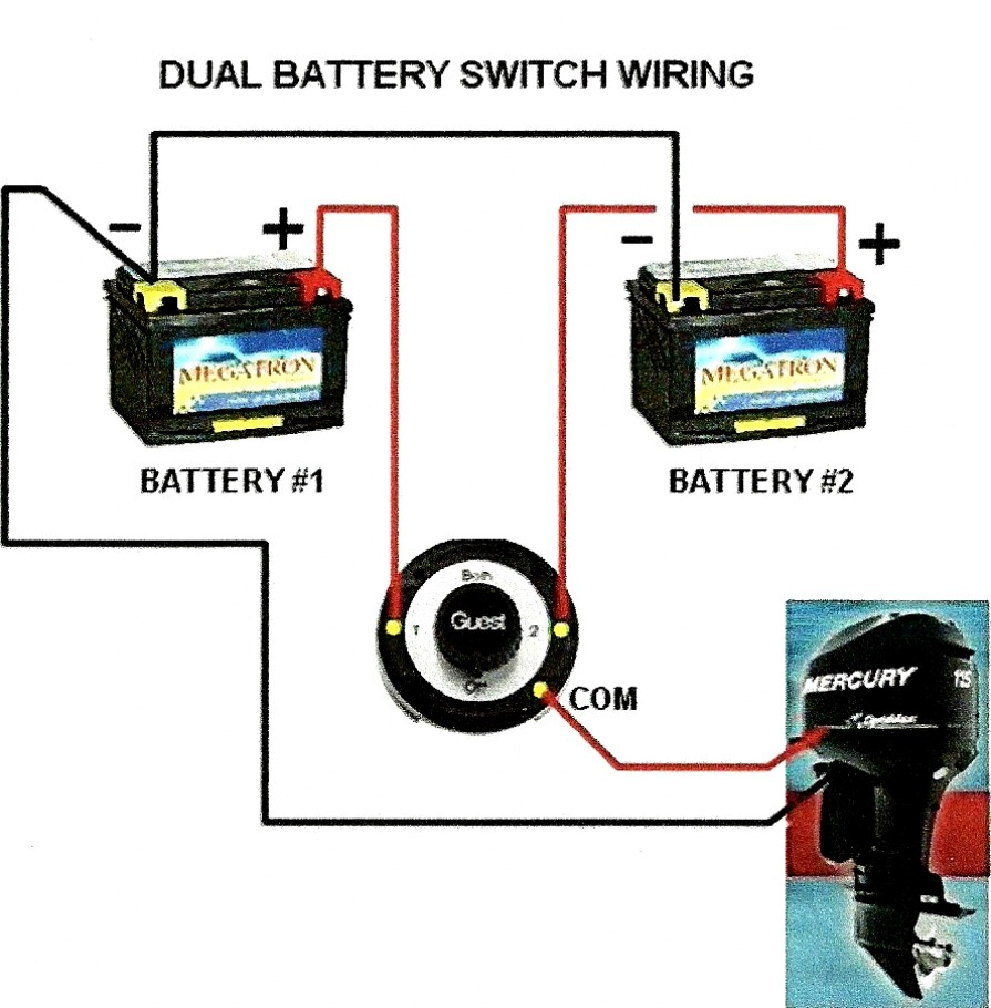
A typical wiring diagram involves connecting the alternator output to the isolator input, then connecting the isolator outputs to the individual battery terminals. Consult your specific isolator's instructions for detailed guidance.
Advantages and Disadvantages of Marine Battery Isolator Switches
| Advantages | Disadvantages |
|---|---|
| Protects starting battery | Slight voltage drop |
| Allows multiple batteries to charge | Requires proper installation |
| Extends battery life | Can be more expensive than simpler solutions |
Best practices include: Using appropriately sized wiring, ensuring proper grounding, regularly inspecting connections, and following manufacturer instructions.
FAQs: What type of isolator do I need? How many batteries can I connect? Where should I install the isolator? Consult your boat's electrical system documentation and a qualified marine electrician for specific advice.
In conclusion, the marine battery isolator switch wiring diagram is the key to a reliable and efficient onboard electrical system. By understanding its function, benefits, and installation process, you can ensure your boat's batteries are always ready to power your adventures. Investing time in learning about your boat's electrical system is an investment in peace of mind on the water.
The alluring scent of zhong guo xiang qi unveiling chinese incense culture
Decoding behr cumberland fog the ultimate neutral paint
Discovering ayatul kursi the throne verse in the quran


