Unlocking Hydraulic Systems Hydraulic Diagram Symbols
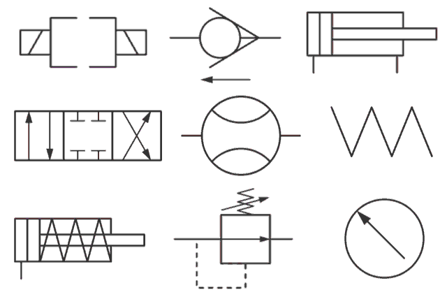
Imagine trying to assemble a complex piece of furniture without instructions. Frustrating, right? Hydraulic systems are no different. They require a clear roadmap for assembly, operation, and maintenance. This roadmap is provided by hydraulic schematic diagrams, and the language of these diagrams is composed of specialized symbols. Understanding these hydraulic schematic diagram symbols is fundamental to anyone working with hydraulic systems, from design engineers to maintenance technicians.
Hydraulic schematic diagrams provide a visual representation of a hydraulic system’s components and their interconnections. They use a standardized set of symbols to represent various elements like pumps, valves, actuators, and reservoirs. This standardized language allows engineers and technicians worldwide to understand and interpret the design and functionality of hydraulic systems regardless of their origin or complexity. Essentially, these symbolic representations serve as the universal language of hydraulics.
The history of hydraulic schematic diagram symbols is intertwined with the development of hydraulic systems themselves. As hydraulic technology evolved, the need for a standardized way to represent these systems became apparent. Early representations were often crude and varied, leading to confusion and misinterpretations. Over time, organizations like the ISO (International Organization for Standardization) developed standardized symbols that are widely used today. This standardization dramatically improved communication and collaboration within the hydraulics industry.
The importance of understanding hydraulic diagrams and their associated symbols cannot be overstated. These diagrams are crucial for designing, building, troubleshooting, and maintaining hydraulic systems. Without a clear understanding of these symbols, misinterpretations can lead to costly errors, system malfunctions, and even safety hazards. Accurate interpretation of hydraulic blueprints is essential for the safe and efficient operation of any hydraulic system.
One of the main issues related to hydraulic schematic diagram symbols is the potential for misinterpretation if not properly understood. This highlights the importance of proper training and education in hydraulic system symbology. Inaccurate interpretation of hydraulic design symbols can lead to incorrect system assembly, faulty operation, or inefficient troubleshooting. Another challenge is keeping up with evolving standards and incorporating new symbols for emerging technologies in hydraulic systems.
A simple example of a hydraulic schematic diagram symbol is the rectangle representing a reservoir. A circle with an arrow inside represents a pump, and a diamond shape with an arrow passing through indicates a directional control valve. Understanding these basic symbols forms the foundation for interpreting more complex diagrams.
Benefit 1: Enhanced Communication: Standardized hydraulic icons enable clear communication between engineers, technicians, and other stakeholders involved in the design, operation, and maintenance of hydraulic systems.
Benefit 2: Efficient Troubleshooting: Hydraulic symbols make it easier to identify the root cause of problems in hydraulic systems. Technicians can quickly locate and diagnose faulty components, minimizing downtime and repair costs.
Benefit 3: Improved Safety: Proper understanding of hydraulic circuit diagram symbols contributes to safer system operation and maintenance by reducing the risk of misinterpretations that could lead to accidents.
Action Plan: Familiarize yourself with basic hydraulic symbols. Practice reading and interpreting simple hydraulic diagrams. Consult reputable resources like ISO standards or industry handbooks. Seek training or mentorship from experienced hydraulics professionals. Regularly review and update your knowledge of hydraulic symbology as the field evolves.
Advantages and Disadvantages of Standardized Hydraulic Symbols
| Advantages | Disadvantages |
|---|---|
| Clear Communication | Requires Training |
| Efficient Troubleshooting | Potential for Misinterpretation |
| Improved Safety | Constant Updates Needed |
Best Practice 1: Adhere to ISO Standards: Always use the latest ISO standards for hydraulic schematic symbols to ensure consistency and clarity.
Best Practice 2: Clear Labeling: Label all components and connections clearly on the diagram.
Best Practice 3: Consistent Scale: Maintain a consistent scale throughout the diagram for accurate representation.
Best Practice 4: Organized Layout: Arrange symbols logically to facilitate easy interpretation.
Best Practice 5: Regular Review: Periodically review and update diagrams to reflect any changes or modifications to the system.
FAQ 1: What is the symbol for a pressure relief valve?
FAQ 2: How is a flow control valve represented in a hydraulic diagram?
FAQ 3: What does a triangle symbol in a hydraulic schematic mean?
FAQ 4: Where can I find a comprehensive list of hydraulic symbols?
FAQ 5: Are there different standards for hydraulic symbols?
FAQ 6: How can I learn to interpret complex hydraulic diagrams?
FAQ 7: What software can be used to create hydraulic diagrams?
FAQ 8: Are there any online resources for learning about hydraulic symbols?
Tips & Tricks: Start with simple diagrams before tackling complex ones. Use a highlighter to trace the flow of hydraulic fluid through the system. Cross-reference symbols with a reliable symbol library. Practice drawing your own diagrams to reinforce your understanding. Join online forums or communities to discuss hydraulic diagrams with other professionals.
In conclusion, hydraulic schematic diagram symbols are the essential building blocks for understanding and working with hydraulic systems. They provide a universal language for communicating system design, facilitating troubleshooting, and ensuring safe operation. Mastering these symbols empowers engineers, technicians, and operators to effectively design, build, maintain, and troubleshoot hydraulic systems. By embracing best practices and continuously updating your knowledge of hydraulic symbology, you can contribute to the safe, efficient, and reliable performance of hydraulic systems across various industries. Understanding these visual cues is not just a technical skill, it's a fundamental requirement for anyone involved in the world of hydraulics. Invest the time to learn these symbols thoroughly, and you'll unlock the key to successfully navigating the intricate world of hydraulic system design and maintenance.
Flat out your mazda cx 5 spare wheel kit guide
Finding comfort in scripture when moving away from family
Engaging 3rd grade activities a comprehensive guide


