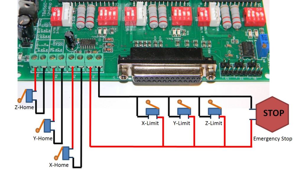
Unlocking Safety: Mastering Limit Switch Series Wiring
Have you ever wondered how machines know when to stop? How a garage door reverses before crushing something, or a conveyor belt halts at just the right moment? The answer often lies in a small but mighty component: the limit switch. And connecting these switches in series opens up a world of control and safety possibilities.
Wiring limit switches in series is a fundamental technique in industrial automation and safety systems. This configuration creates a circuit where all switches must be activated for the circuit to be complete. This method ensures multiple safety checks are satisfied before a machine can operate, preventing accidents and damage. Think of it as a chain; if one link breaks, the entire chain is ineffective. Similarly, if any switch in the series is triggered, the circuit is broken, halting the operation.
The history of limit switches is intrinsically linked to the rise of automated machinery. As industries adopted more complex systems, the need for reliable safety mechanisms became paramount. Early limit switches were mechanical contraptions, evolving over time into the electromechanical and solid-state devices we use today. The principle of series wiring emerged as a simple yet effective way to increase the safety and reliability of these systems.
The importance of correctly connecting limit switches in series cannot be overstated. Incorrect wiring can lead to hazardous situations, bypassing safety measures and potentially causing injury or equipment damage. A common issue is improper wiring leading to a normally closed circuit, meaning the safety mechanism is bypassed unless the switch is activated, the opposite of the intended behavior. Understanding the underlying principles of series circuits is crucial for ensuring proper implementation.
Let's define what we mean by "series wiring." In a series circuit, the components are connected end-to-end, forming a single path for the current to flow. In the context of limit switches, this means that the current flows through each switch sequentially. If any switch opens (is triggered), the circuit is broken, and the current stops. A simple example is a garage door with two limit switches, one at the top and one at the bottom. Wiring these in series ensures that the door motor stops when either limit is reached, preventing the door from traveling too far in either direction.
One benefit of series wiring is enhanced safety. By requiring multiple switches to be activated, the system is less likely to fail due to a single switch malfunction. Another advantage is increased control. Series wiring allows for complex control sequences, such as requiring multiple safety checks before a machine starts operating. Finally, series wiring can simplify troubleshooting. If the circuit fails, checking each switch in the series can quickly pinpoint the faulty component.
To successfully wire limit switches in series, follow these steps: (1) Identify the normally open (NO) or normally closed (NC) contacts on each switch. (2) Connect the NO contact of the first switch to the power supply. (3) Connect the common (C) contact of the first switch to the NO contact of the second switch. (4) Repeat this process for all switches in the series. (5) Connect the C contact of the last switch to the input of the controlled device.
Advantages and Disadvantages of Wiring Limit Switches in Series
| Advantages | Disadvantages |
|---|---|
| Enhanced Safety | Increased Complexity (for numerous switches) |
| Increased Control | Single Point of Failure (one open switch stops the entire circuit) |
| Simplified Troubleshooting |
Best Practices: 1. Use appropriate wire gauge. 2. Ensure proper grounding. 3. Use wire ferrules to prevent fraying. 4. Label all wires clearly. 5. Test the circuit thoroughly before operation.
Real World Examples: 1. Garage doors, 2. Conveyor belts, 3. Industrial presses, 4. Robotic arms, 5. CNC machines
Challenges & Solutions: 1. Wiring errors – double-check connections. 2. Switch malfunction – replace faulty switches. 3. Environmental factors – use sealed switches. 4. Voltage drops – use appropriate wire gauge. 5. Mechanical interference – adjust switch placement.
FAQ: 1. What is a limit switch? 2. What is series wiring? 3. Why wire limit switches in series? 4. What are the different types of limit switches? 5. How do I troubleshoot a series circuit? 6. What safety precautions should I take? 7. Can I wire different types of switches in series? 8. What are the limitations of series wiring?
Tips and tricks: Use a multimeter to test continuity, consult wiring diagrams, and always prioritize safety.
In conclusion, wiring limit switches in series is a crucial technique for enhancing safety and control in a variety of applications. By understanding the principles of series circuits and following best practices, you can implement reliable and effective safety systems. From the simplest garage door to the most complex industrial machinery, the proper use of limit switches ensures safe and efficient operation. Take the time to learn the fundamentals, apply the tips and tricks, and remember that prioritizing safety is paramount. Investing in understanding and implementing this fundamental electrical principle will undoubtedly pay dividends in the long run, protecting both personnel and equipment. Don't underestimate the power of this small component; it plays a significant role in keeping our world running smoothly and safely.
Unlocking creativity weapon design for games and film
Conquering the ford f 150 lug nut socket size and more
The allure of deep teal exploring sherwin williams rich hue


