Unlocking the Power of Contactor and Relay Coils
Ever wondered about the silent workhorse behind many electrical systems? It's the unsung hero, the coil – specifically, the coil for a contactor or relay. These small but mighty components are the driving force behind switching high-power circuits, enabling everything from industrial automation to simple household appliances.
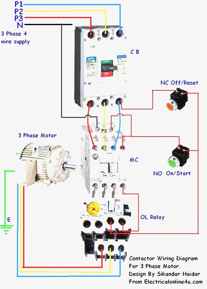
The contactor or relay coil acts as an electromagnetic switch. When energized, it creates a magnetic field that pulls in a metal armature, closing electrical contacts and allowing current to flow through a separate, higher-power circuit. This allows for the control of significant electrical loads with a relatively small control signal.
Understanding the function of a contactor or relay coil is crucial for anyone working with electrical systems. Whether you're an engineer designing complex automation systems or a homeowner troubleshooting a faulty appliance, a grasp of coil operation can be invaluable. This article explores the intricacies of these essential components, providing a comprehensive guide to their operation, benefits, and troubleshooting.
The history of electromagnetic relays, the precursors to modern contactors, can be traced back to the early 19th century. Joseph Henry, an American scientist, is often credited with developing the first practical electromagnetic relay in the 1830s. These early devices paved the way for the development of more robust contactors, which are essentially heavy-duty relays capable of handling much higher currents.
The importance of the contactor or relay coil lies in its ability to isolate control circuits from power circuits. This enhances safety by preventing high voltages from reaching sensitive control components. Furthermore, coils allow for remote switching, enabling centralized control of distant electrical equipment. Without these crucial components, many modern electrical systems simply wouldn't be possible.
A contactor coil, in essence, is a wire wound around a ferromagnetic core. When current flows through the coil, it creates a magnetic field. This magnetic field attracts a metal armature, completing the electrical circuit. The coil's voltage rating must match the control circuit voltage, while the contactor’s contact rating must match the load current. For example, a 24V coil will be energized by a 24V control signal.
Three key benefits of using contactor or relay coils include enhanced safety, remote operation, and automation. Enhanced safety is achieved by isolating low-voltage control circuits from high-voltage power circuits. Remote operation enables control of equipment from a distance, increasing efficiency and convenience. Finally, automation is facilitated by the ability to programmatically control contactors and relays, optimizing processes and reducing manual intervention.
One common issue with contactor coils is overheating. This can be caused by excessive current, voltage fluctuations, or a faulty coil. Troubleshooting often involves checking the coil voltage, resistance, and ensuring proper cooling.
Advantages and Disadvantages of Contactor/Relay Coils
| Advantages | Disadvantages |
|---|---|
| Enhanced Safety | Potential for Coil Burnout |
| Remote Operation | Sensitivity to Voltage Fluctuations |
| Automation Capabilities | Requires External Power Source |
Best Practices for Contactor/Relay Coils:
1. Ensure proper voltage supply to the coil.
2. Protect the coil circuit with a fuse or circuit breaker.
3. Provide adequate ventilation to prevent overheating.
4. Regularly inspect the coil for signs of damage or wear.
5. Choose the appropriate coil voltage and contact rating for the application.
Frequently Asked Questions:
1. What is the difference between a contactor and a relay? - Contactors typically handle higher currents than relays.
2. What causes a contactor coil to burn out? - Overvoltage, overcurrent, or a short circuit.
3. How can I test a contactor coil? - Measure its resistance using a multimeter.
4. What is the function of a contactor coil? - To create a magnetic field that closes the contactor's contacts.
5. How do I choose the right contactor coil voltage? - Match it to the control circuit voltage.
6. What are the symptoms of a faulty contactor coil? - Overheating, chattering, or failure to operate.
7. How can I prevent contactor coil burnout? - Ensure proper voltage, current protection, and ventilation.
8. What are some common applications of contactors? - Motor control, lighting control, and HVAC systems.
Tips and Tricks: Use a surge suppressor to protect the coil from voltage spikes. Regularly clean the contactor contacts to ensure reliable operation. Consult the manufacturer's datasheet for specific coil specifications and operating instructions.
In conclusion, the contactor or relay coil, though seemingly a small component, plays a pivotal role in a wide range of electrical systems. From ensuring safety through circuit isolation to enabling sophisticated automation, these electromagnetic workhorses are indispensable. Understanding their operation, benefits, and potential issues is crucial for anyone working with electrical equipment. By following best practices and staying informed about the latest advancements, you can harness the full power and reliability of these essential components. Taking the time to understand and maintain these components will ensure the smooth and efficient operation of your electrical systems for years to come. Explore further resources and expand your knowledge to optimize your utilization of contactor and relay coils.
A culinary tapestry exploring the ann arbor restaurant scene
Transform your home with behr marquee paint colors
Reliable power on the go your guide to costco car jump starters


