Unlocking Your Gem Boat Lift Electrical Blueprint
Imagine effortlessly gliding your boat onto a secure lift at the end of a perfect day on the water. A properly functioning boat lift is a waterfront essential, and at the heart of its operation lies the gem boat lift electrical schematic – the roadmap that powers your lift's smooth and reliable performance. Understanding this diagram is crucial for maintaining, troubleshooting, and even upgrading your boat lift system.
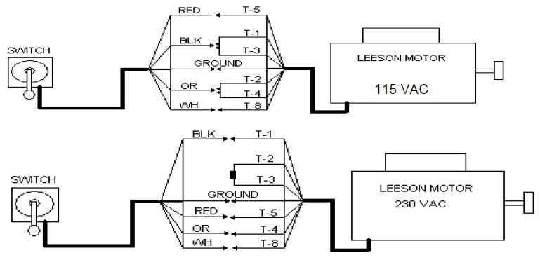
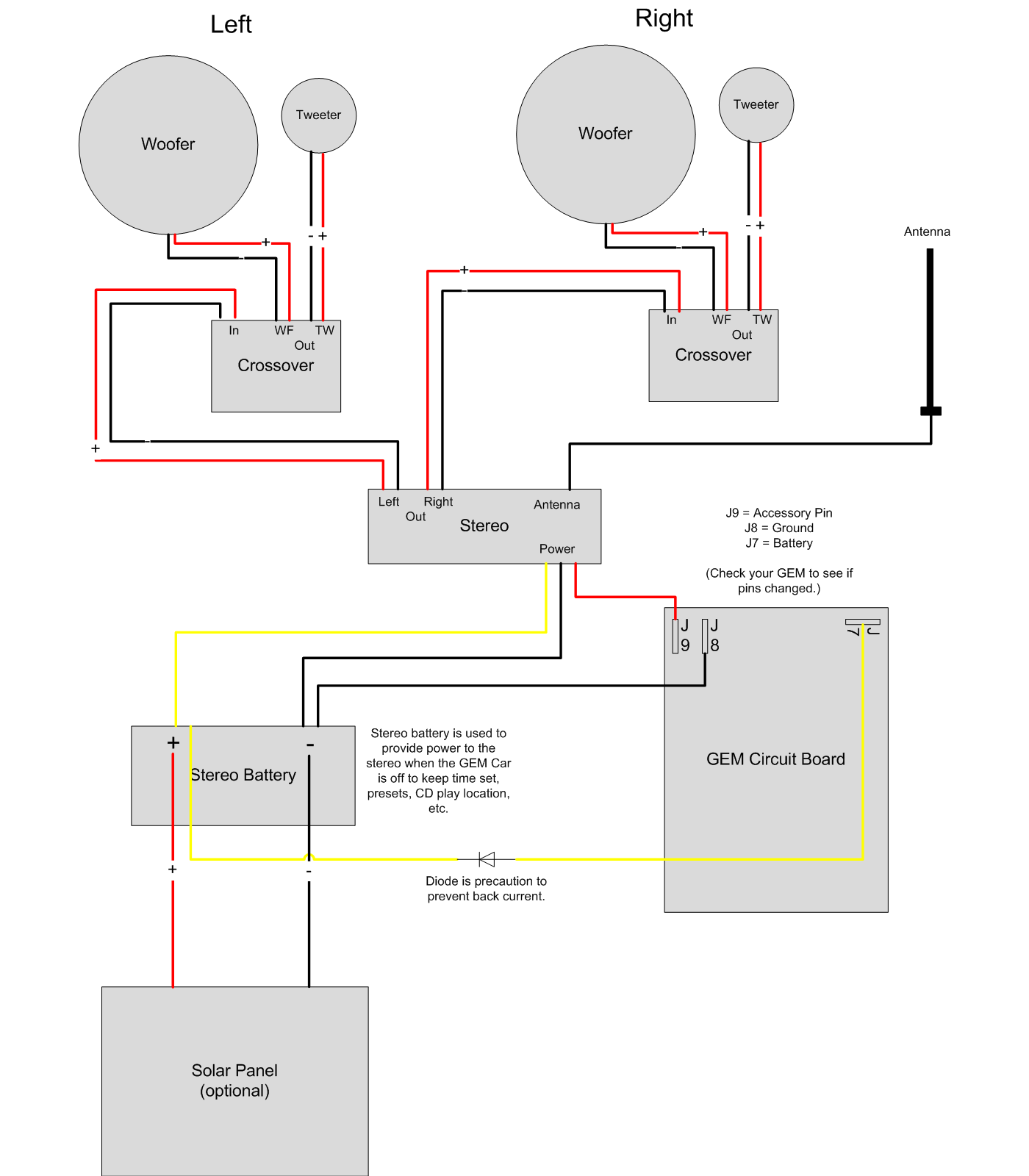
Whether you're a seasoned boat owner or a newcomer to the waterfront lifestyle, a firm grasp of your Gem boat lift's electrical system is essential. This involves familiarizing yourself with the intricacies of the Gem boat lift wiring diagram, which serves as the blueprint for the entire electrical setup. It details the connections between various components, including the motor, switches, and safety devices, providing a visual representation of the power flow.
Historically, boat lifts were simpler mechanisms, often relying on manual or basic electrical systems. As technology advanced, so did boat lift designs, incorporating more sophisticated electrical components and controls. The Gem boat lift wiring diagram reflects this evolution, providing a detailed map of the more complex circuitry involved in modern lifts.
The importance of a Gem boat lift wiring schematic cannot be overstated. It's the key to diagnosing electrical issues, ensuring safe operation, and undertaking any repairs or modifications. Without a clear understanding of this diagram, troubleshooting can become a frustrating and potentially dangerous endeavor.
One common issue boat owners face is a malfunctioning lift motor. This can be caused by various electrical problems, such as a blown fuse, a faulty switch, or a damaged wire. Referring to the Gem boat lift wiring diagram allows you to pinpoint the source of the problem quickly and efficiently, saving you time and potentially costly repairs. Other issues can include limit switch malfunctions, control box problems, and wiring corrosion due to the marine environment.
A Gem boat lift wiring diagram uses standardized symbols to represent various electrical components. For example, a circle with a cross inside typically represents a switch, while a zig-zag line denotes a resistor. Understanding these symbols is crucial for interpreting the diagram correctly.
Benefit 1: Troubleshooting made easy. With a Gem boat lift wiring schematic, you can quickly identify the source of electrical problems, saving time and money on repairs.
Benefit 2: Enhanced Safety. Understanding the wiring diagram allows you to ensure all safety features are correctly wired and functioning, preventing accidents and protecting your boat.
Benefit 3: Simplified Upgrades. If you decide to upgrade your lift system, the wiring diagram will be indispensable for integrating new components seamlessly.
If your lift isn't working correctly, consult the Gem boat lift wiring diagram. Trace the wiring from the power source to the motor, checking for breaks, loose connections, and damaged components. A multimeter can be used to test for continuity and voltage.
Checklist for Electrical Maintenance:
1. Inspect wiring for damage or corrosion.
2. Check all connections for tightness.
3. Test all switches and safety devices.
4. Inspect the motor for signs of wear or overheating.
Advantages and Disadvantages of DIY Electrical Work
| Advantages | Disadvantages |
|---|---|
| Cost Savings | Risk of Injury or Damage |
| Sense of Accomplishment | Potential for Code Violations |
Best Practices:
1. Always disconnect the power before working on any electrical components.
2. Use marine-grade wiring and connectors to resist corrosion.
3. Properly ground all electrical components.
4. Consult a qualified electrician if you are unsure about any aspect of the wiring.
5. Regularly inspect and maintain your electrical system.
FAQ:
Q: Where can I find my Gem boat lift wiring diagram? A: Contact the manufacturer or check the owner's manual.
Q: What should I do if my lift motor isn't working? A: Consult the wiring diagram to troubleshoot the problem.
Q: Can I upgrade my lift motor? A: Yes, but consult the wiring diagram to ensure compatibility.
Q: How often should I inspect my electrical system? A: At least annually, or more frequently in harsh marine environments.
Q: What type of wiring should I use? A: Marine-grade wiring.
Q: What safety precautions should I take? A: Always disconnect power before working on the system.
Q: What are common problems with boat lift wiring? A: Corrosion, loose connections, and faulty switches.
Q: How can I prevent electrical problems? A: Regular maintenance and inspections.
Tips and Tricks: Apply dielectric grease to all connections to prevent corrosion. Use zip ties to secure wiring and prevent chafing.
Understanding your Gem boat lift wiring diagram is not just about fixing problems; it's about ensuring the longevity and reliable performance of your boat lift system. By familiarizing yourself with the electrical schematic, you can perform routine maintenance, diagnose issues effectively, and even undertake upgrades with confidence. This proactive approach not only saves you time and money but also enhances safety and ensures countless enjoyable days on the water. By understanding the layout and function of each component, you can confidently maintain and troubleshoot your system, saving you time, money, and frustration. This knowledge empowers you to identify potential problems early on, preventing costly repairs down the road. Embrace the power of the Gem boat lift wiring diagram, and keep your lift running smoothly for years to come.
Decoding the secrets of dc voltage symbols on meters
Unraveling the mystery peter ellis kings guard
Understanding federal salaries in nashville tennessee


