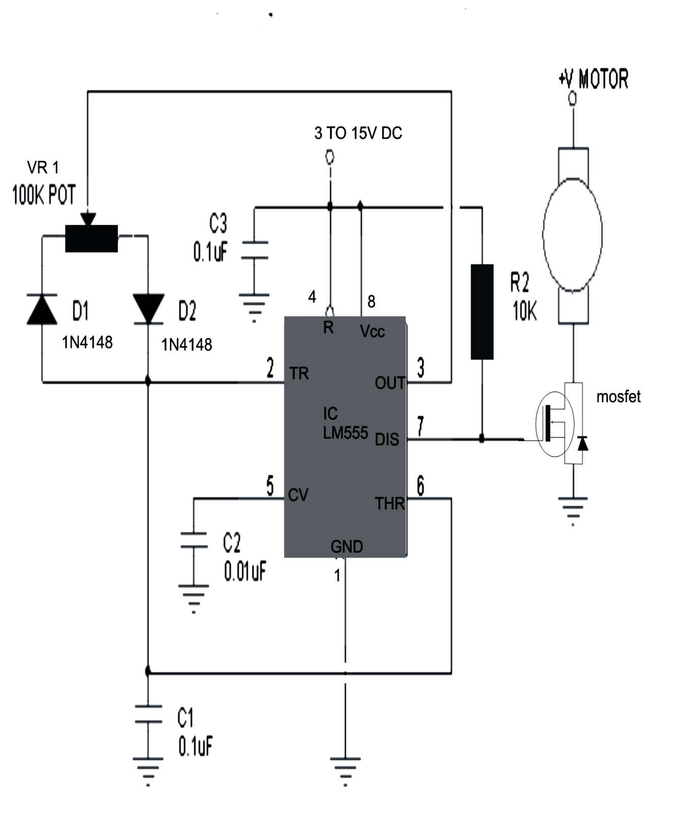
Mastering DC Motor Control Schematics
Ever wondered how those tiny motors whirring inside your appliances know exactly when to spin, how fast, and in which direction? The secret lies in the carefully crafted DC motor control circuit, a network of electrical components meticulously arranged to orchestrate the motor's every move. Understanding the blueprint for this control system, commonly known as a wiring diagram, is like unlocking the language of the motor, empowering you to control its performance with precision.
DC motor control circuits aren't just about switching a motor on and off. They're about harnessing the power of electricity to achieve precise control over speed, direction, and even torque. Whether it's the delicate movements of a robotic arm or the powerful thrust of an electric vehicle, the underlying principle remains the same: the schematic dictates the flow of power, transforming electrical energy into controlled mechanical motion. This mastery of motor control is essential across diverse fields, from industrial automation and robotics to consumer electronics and automotive engineering.
The origins of DC motor control schematics can be traced back to the early days of electrical engineering, evolving alongside advancements in motor technology and control systems. Early diagrams were relatively simple, focusing primarily on basic on/off control. However, as the demand for more sophisticated motor control grew, the complexity of these schematics increased, incorporating components like relays, transistors, and integrated circuits to enable precise speed regulation, directional control, and dynamic braking.
One of the primary challenges in working with DC motor control circuits lies in interpreting and understanding the intricacies of the wiring diagrams. These diagrams can range from simple representations for basic on/off control to complex layouts for advanced control systems involving multiple motors, feedback loops, and programmable logic controllers. Misinterpreting a single connection can lead to malfunctions, damage to the motor, or even safety hazards. Therefore, a thorough understanding of the symbols, conventions, and underlying principles of these diagrams is crucial for safe and effective motor control implementation.
A DC motor control schematic is essentially a roadmap, guiding the flow of electricity to control the motor. It visually represents the electrical connections between the various components, including the power source, motor, switches, relays, and control circuits. By following the schematic, one can accurately connect the components and ensure proper operation of the motor. A simple example would be a basic on/off control circuit using a single switch to control the power supply to the motor. More complex diagrams might involve multiple switches, relays, and even microcontrollers for precise speed and direction control.
Three key benefits of using wiring diagrams are: Clarity: They offer a clear visual representation of the circuit, aiding in troubleshooting and modifications. Safety: Proper diagrams ensure safe wiring practices, minimizing the risk of electrical hazards. Efficiency: Diagrams streamline the installation process, reducing errors and saving time.
Advantages and Disadvantages of Using Wiring Diagrams
| Advantages | Disadvantages |
|---|---|
| Clear Visual Representation | Can be complex for intricate systems |
| Enhanced Troubleshooting | Requires understanding of electrical symbols |
| Simplified Installation | Outdated diagrams can lead to errors |
Best practices include using standard symbols, clear labeling, proper wire sizing, and thorough testing.
Real-world examples include controlling motors in robots, conveyor belts, and electric cars.
Challenges include component failure and wiring errors. Solutions involve troubleshooting techniques and preventative maintenance.
FAQs cover topics like reading diagrams, choosing the right components, and troubleshooting common problems. For example, What is the purpose of a diode in a DC motor circuit? A diode protects against voltage spikes.
Tips include double-checking connections and using appropriate safety measures.
In conclusion, DC motor control schematics are essential tools for anyone working with electric motors. They provide a clear blueprint for building and troubleshooting control circuits, enabling precise control of motor speed, direction, and performance. Understanding and applying the principles of these diagrams is crucial for a range of applications, from simple on/off control to complex automation systems. Mastering these schematics empowers you to harness the full potential of electric motors, opening up a world of possibilities for innovation and design. By taking the time to study and understand DC motor control wiring diagrams, you equip yourself with the knowledge to design, build, and maintain efficient and reliable motor control systems. This expertise is valuable across various industries, offering opportunities for career advancement and enabling you to contribute to the ongoing evolution of motor control technology. Invest in your understanding of these diagrams, and you invest in your future.
Unraveling the enigma of milk duds net worth
The downfall of senator joseph mccarthy
Conquer the road mastering ford f250 torque specs


